Unit 11 · Topic 11.5 · about 30 minutes · 7 parts · 12 scored checks, 2 of them multiple choice, plus 2 from earlier lessons
AP Physics 2: Algebra-Based 11.5: Compound Direct Current (DC) Circuits
Unit 11: 15 to 18% of the multiple-choice section
What you'll be able to do
- Describe the equivalent resistance of resistors connected in series, in parallel, or in a mix of both.
- Describe a circuit whose wires or battery have resistance, including a battery's emf and the potential difference across its terminals.
- Describe how ammeters and voltmeters are connected to measure current and potential difference, and how a real meter changes what it measures.
Key vocabulary
| Term | What it means | The exam trap |
|---|---|---|
| Series connection | A connection in which any charge passing through one element must pass through every element in it, with no other path, so each element carries the same current. | A schematic may draw elements in series around corners or on opposite sides of the page, so a bend in the wire does not end a series connection. |
| Parallel connection | A connection in which charge can take one of two or more paths between the same two points, so each path has the same potential difference across it. | Some books write a parallel pair as , read as R2 in parallel with R3, so do not read the two bars as a division sign. |
| Equivalent resistance | The resistance of the single resistor that would draw the same current from the same potential difference as a whole group of resistors. | The parallel rule gives first, so take the inverse at the end before you write down a resistance. |
| Emf | The potential difference a battery would supply if it were ideal, written and measured in volts. | The symbol is a script E, and despite the name electromotive force it is a potential difference, measured in volts. |
| Internal resistance | The resistance of the materials inside a real battery. | A problem may give a battery's internal resistance only in words and draw an ordinary battery symbol, so read the stem for before you treat a battery as ideal. |
| Ammeter | A meter that measures the current at one point in a circuit; an ideal ammeter has zero resistance. | Ammeter readings are often given in milliamperes, so divide by 1000 to get amperes before you use them with volts and ohms. |
| Voltmeter | A meter that measures the potential difference between two points in a circuit; an ideal voltmeter has infinite resistance. | A voltmeter reads a potential difference between two points, never a potential at one point, so a question about the potential at a point needs a reference point to measure from. |
 Tap to open the picture full size
Part 1 Think first Why the headlights dip
Commit to a guess first. Being wrong now makes the right idea stick better.
Predict first
A car's headlights are on with the engine off. When the driver turns the key, the starter motor draws a very large current to crank the engine, and the headlights dim for a moment, then brighten again once the starter stops. The headlights and the starter motor are each wired across the battery in a branch of their own. Why do the headlights dim?
In short. Elements in series have the same current and elements in parallel have the same potential difference, a group of resistors acts like one equivalent resistance, and real batteries and meters have resistance that changes what a circuit does.
- Series: . Parallel: , so each added path lowers the equivalent resistance.
- A battery with internal resistance has a terminal potential difference , which equals its emf only when there is no current in it.
- An ammeter goes in series and an ideal one has zero resistance; a voltmeter goes in parallel and an ideal one has infinite resistance.
Part 2 Learn it Series, parallel, real batteries and meters
2a. Series and parallel
Elements in a circuit can be connected in series, in parallel, or in a mix of the two.
In a series connection, any charge that passes through one element must go on through every other element in that connection, with no other path available. So the current is the same in every element in series. A battery and two bulbs on a single path with no branches are all in series.
In a parallel connection, charge can take one of two or more paths between the same two points. Each path begins at one of those points and ends at the other, so the potential difference across each path is the same. Two bulbs each joined straight across one battery are in parallel.
Two elements can be neither. Take a bulb on the main wire and a bulb on one of two branches after it. Some of the charge leaving the first takes the other branch, so they are not in series, and they do not join the same two points, so they are not in parallel.
Equal currents do not prove a series connection: two identical bulbs in parallel carry equal currents too.
Quick check · Select all
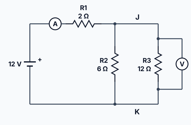
A battery's positive terminal is joined by a wire to resistor . Past the wire is J, and resistors , 6 , and , 12 , each join J to a wire K that returns to the battery's negative terminal. All the wires are ideal. Which two statements are true? Pick two.
Select 2 answers, then check.
2b. Equivalent resistance
A group of resistors can be analyzed as though it were one resistor with an equivalent resistance, : the single resistance that would draw the same current from the same potential difference.
In series the resistances add:
Charge has to get through every one of them, so a 2 and a 4 resistor in series act like 6 .
In parallel the inverses add:
A 3 and a 6 resistor in parallel give , so , less than either resistor alone. Each resistor added in parallel is one more path for charge, so the equivalent resistance goes down, however large the added resistor is. Two equal resistors in parallel give half the resistance of one.
A mixed circuit is reduced one group at a time. Combine resistors that are plainly in parallel, or plainly in series, into one equivalent resistor, redraw the circuit, and repeat until one resistor is left.
Quick check · Rank it
Five arrangements are made from identical resistors, each of resistance . Arrangement 1 is one resistor. Arrangement 2 is two resistors in series. Arrangement 3 is two resistors in parallel. Arrangement 4 is three resistors in parallel. Arrangement 5 is one resistor in series with a pair of resistors that are in parallel with each other. Rank the arrangements by equivalent resistance.
Greatest equivalent resistance first
Give each one a place, 1 for first. Give two the same place if they are equal.
Your ranking: none yet
2c. Real wires and real batteries
So far every battery and wire has been ideal. An ideal battery has negligible internal resistance, and an ideal wire has negligible resistance. Copper leads come close: their resistance is normally far smaller than that of the bulbs and resistors in a circuit, so it can be neglected. That works only when the circuit contains other elements that do have resistance.
A real battery has an internal resistance, . Treat it as a resistor in series with an ideal battery and the rest of the circuit. The emf, , is the potential difference the battery would supply if it were ideal: what a voltmeter reads across the terminals when there is no current in the battery.
With a current in the battery, part of the emf is taken up across , and the terminals show less:
A 1.5 V cell with delivering 0.50 A has V across its terminals. The more current, the lower the terminal potential difference, which is why the headlights dip while the starter cranks.
Quick check · Calculate
A battery with an emf of 9.0 V and an internal resistance of 0.50 is connected to a 4.0 resistor by ideal wires. What is the potential difference across the battery's terminals? Give your answer to the nearest 0.1 V.
2d. Measuring with meters
An ammeter measures the current at one point in a circuit. The charge you want to count must pass through it, so it goes in series with the element whose current you want: open the circuit beside that element and put the ammeter in the gap. An ideal ammeter has zero resistance, so it does not change the current in the element it is in series with.
A voltmeter measures the potential difference between two points. Its two leads go to those points, in parallel with the element whose potential difference you want, without opening the circuit. An ideal voltmeter has infinite resistance, so no charge flows through it.
In the circuit at the top of this lesson, the ammeter on the main wire reads the battery's current, and the voltmeter across reads the potential difference across .
Real meters are not ideal. A real ammeter has a little resistance, so it lowers the current it measures. A real voltmeter lets a little charge through, so it lowers the resistance of what it is connected across. Either way the meter changes the circuit it measures. Unless a question says otherwise, treat every meter as ideal.
Quick check · Multiple choice
A bulb, a resistor and a battery are joined by ideal wires on a single path with no branches, and the bulb glows. A student wants the bulb's current, so she connects an ideal ammeter from one contact of the bulb to its other contact. What happens?
Part 3 Watch it done Reduce the circuit, then read the meters
Predict first, then watch each step, then finish the problem yourself.
In the circuit at the top of this lesson, an ideal 12 V battery drives current through an ideal ammeter and on the top wire. Past , resistors and each join wire J to wire K, and an ideal voltmeter is wired across . The wires are ideal. What does the voltmeter read?
Predict first
Before you open the first step, predict: what does the voltmeter across read?
Step 1 · Sort out what is in series and what is in parallel
and both join J to K, so they are in parallel, and the voltmeter reads the potential difference across both of them. All of the battery's charge passes through the ammeter, through and then through the pair, so is in series with the pair taken as a whole. The ideal meters change nothing: the ammeter has zero resistance, and no charge flows through the voltmeter.
Step 2 · Plan the reduction
Replace the pair by one resistor , with . Then . The battery is ideal, so its 12 V is across and the current through the ammeter is . That same current passes through the pair, so the voltmeter reads .
Why this step?
Why combine and before adding ?
is not in series with alone or with alone, since charge leaving can take either branch. It is in series with the pair taken as a whole, so the pair has to become one equivalent resistor before the series rule applies.
Your step · Calculate
Finish it. An ideal 12 V battery, an ideal ammeter and a 2 resistor are in series on the top wire of a circuit. Past , a 6 resistor and a 12 resistor each join the top wire to the bottom wire, which returns to the battery, and an ideal voltmeter is wired across . The wires are ideal. What does the voltmeter read? Give your answer to the nearest 0.1 V.
V
Part 4 Try it Rank, decide, sort
 Tap to open the picture full size
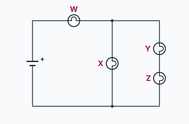
Rank the bulbs below before you work anything out. Then check your ranking: reduce the circuit, and use the power from the last lesson.
Try it · Rank it
Four identical bulbs are joined to an ideal battery by ideal wires. Bulb W is on the main wire, and all of the battery's current passes through it. Past W the circuit splits into two branches that meet again before the wire returns to the battery: one branch holds bulb X alone, and the other holds bulbs Y and Z, one after the other. Treat each bulb's resistance as fixed. Rank the bulbs by brightness.
Brightest first
Give each one a place, 1 for first. Give two the same place if they are equal.
Your ranking: none yet
Now give the battery some internal resistance. Predict first: does adding a bulb change the one already lit?
Try it · Decide and justify
A flashlight battery with some internal resistance lights one bulb, joined by ideal wires. A second bulb, identical to the first, is then connected in parallel with it. Treat each bulb's resistance as fixed. Does the first bulb get dimmer?
Which reason supports your answer?
Try it · Sort it
Each card describes the wires in a circuit with a real battery. Tap a card, then choose whether a careful calculation could neglect the resistance of those wires.
Can be neglected
Cannot be neglected
Part 5 Explain it Draw the meters, then argue two ways
On the exam this is handwritten, so answer on paper first. Nothing you type here leaves this page. Then check your answer against the model and each scoring point.
Free response is 50% of the exam score. This one is shaped like Question 4, Qualitative/Quantitative Translation.
Free-response practice · Question 4 style
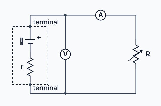
A student connects a battery of emf and internal resistance to a variable resistor of resistance , using ideal wires. She uses an ideal ammeter to measure the current in the battery and an ideal voltmeter to measure the potential difference across the battery's terminals.
(a) On paper, draw a schematic of the circuit, showing the battery as an ideal battery in series with its internal resistance, and both meters connected correctly. Do this by hand before you open the model.
(b) The student makes smaller. Without using equations, explain how the voltmeter reading changes.
(c) Derive an expression for the voltmeter reading in terms of , and , and explain how it supports your answer to (b).
Model answer
(a) Compare your drawing with the schematic below. It is right if the ideal battery and are in series inside the battery, the ammeter is in series in the loop, and the voltmeter joins the two terminals, outside . Where each part sits on your page does not matter.
(b) The reading goes down. A smaller lowers the total resistance of the loop, so the battery carries more current. More current in the battery means a larger potential difference across its internal resistance, which leaves less of the emf across the terminals.
(c) is in series with , so , and the reading is . As gets smaller, gets smaller, so the reading falls, as argued in (b). When is much larger than the reading is close to , the value it would have with no current.
 Tap to open the picture full size
Score your own answer. This is a self-check, not a grade. Tick each point your answer makes.
Part 6 Check yourself Adding resistors to a real battery
Both case questions use the table.
A student connects 12 resistors one at a time in parallel across the terminals of a battery, using ideal wires. An ideal ammeter reads the current in the battery, and an ideal voltmeter reads the potential difference across its terminals. With no resistor connected there is no current in the battery.
| Resistors connected | Ammeter (A) | Voltmeter (V) |
|---|---|---|
| 0 | 0.00 | 6.00 |
| 1 | 0.46 | 5.54 |
| 2 | 0.86 | 5.14 |
| 3 | 1.20 | 4.80 |
| 4 | 1.50 | 4.50 |
Case question 1 · Calculate
Using the table of meter readings: what is the internal resistance of the battery? Give your answer to the nearest 0.1 .
Case question 2 · Multiple choice
Using the table of meter readings: why does the ammeter reading rise each time another 12 resistor is connected?
The rest stand on their own and do not use the case.
Check yourself · Spot the error
A student plans how to measure the current in a resistor and the potential difference across it, in a circuit that is already working. Tap the first line that goes wrong.
Check yourself · Decide and justify
Two 100 k resistors are in series with an ideal 9.0 V battery, joined by ideal wires, so each resistor has 4.5 V across it. A student connects a cheap analog voltmeter, whose own resistance is also 100 k, across one of the resistors. Is the reading lower than 4.5 V?
Which reason supports your answer?
Part 7 Keep it Bring back earlier ideas
Series and parallel rest on the last two lessons: the power that sets a bulb's brightness, and loops with elements in common. Pulling them back up is what makes them last.
From 11.4 Electric Power · Rank it
A student measures three glowing bulbs, each in a circuit of its own. Bulb X carries 0.50 A with 6.0 V across it. Bulb Y carries 0.25 A with 12 V across it. Bulb Z carries 1.0 A with 2.0 V across it. Assume a bulb's brightness depends only on its power. Rank the bulbs by brightness.
Brightest first
Give each one a place, 1 for first. Give two the same place if they are equal.
Your ranking: none yet
From 11.2 Simple Circuits · Select all
A battery is joined to two branches by ideal wires. One branch holds bulb P alone. The other holds switch S, bulb Q and bulb R, one after another. With S closed all three bulbs glow. S is then opened. Which two statements are true? Pick two.
Select 2 answers, then check.
In three lines
- Series elements have the same current and ; parallel paths have the same potential difference and , so each added path lowers .
- A real battery is an ideal battery in series with its internal resistance , and its terminals show .
- Ammeters go in series and ideal ones have zero resistance; voltmeters go in parallel and ideal ones have infinite resistance.
Exam strategy for this topic
- Section I, Multiple Choice: 42 questions in 85 minutes.
- Section II, Free Response: 4 questions in 95 minutes.
- This lesson's Explain it is shaped like free-response question 4, Qualitative/Quantitative Translation.
- A four-function, scientific, or graphing calculator is allowed on both sections of the exam.
Reduce a circuit one group at a time: combine what is plainly in parallel or plainly in series, redraw, and repeat, then work back out to each element. Put ammeters in series and voltmeters in parallel, and use whenever a battery has internal resistance.
Questions students ask
How do you find equivalent resistance in series and in parallel?
In series, add the resistances: . In parallel, add the inverses: , then take the inverse. A 3 and a 6 resistor give 9 in series and 2 in parallel.
Why does adding a resistor in parallel lower the total resistance?
Each resistor in parallel is one more path between the same two points, so more charge can flow for the same potential difference. The equivalent resistance of a parallel group is smaller than its smallest resistor.
What is the difference between emf and terminal voltage?
The emf, , is the potential difference across a battery's terminals with no current in it. With a current , part of it is taken up across the internal resistance , and the terminals show .
Where do you connect an ammeter and a voltmeter?
An ammeter goes in series with the element whose current you want, so all of that current passes through it. A voltmeter goes in parallel, its leads on the two points whose potential difference you want.
Why should an ammeter have zero resistance and a voltmeter infinite resistance?
So that connecting them does not change the circuit. Zero resistance in series adds nothing to the loop, and infinite resistance in parallel lets no charge through. Real meters fall short of both, so they change slightly what they measure.
Beyond the AP Exam
College Board sets this limit on what the AP Exam asks about this topic. Anything past it is not on the exam.
AP Physics 2 only expects students to qualitatively discuss how a nonideal ammeter or voltmeter will affect the results of measurements. Unless otherwise stated, all batteries, wires, and meters are assumed to be ideal. Circuits with batteries of different potential differences connected in parallel will not be assessed.
Course alignment, for teachers
AP Physics 2: Algebra-Based topic 11.5, Unit 11: Electric Circuits.
- Skill 1.A: Create diagrams, tables, charts, or schematics to represent physical situations.
- Skill 2.A: Derive a symbolic expression from known quantities by selecting and following a logical mathematical pathway.
- Skill 2.C: Compare physical quantities between two or more scenarios or at different times and locations in a single scenario.
- Skill 3.B: Apply an appropriate law, definition, theoretical relationship, or model to make a claim.
This lesson maps all 20 essential knowledge statements of the topic to the part that teaches each one: 20 are checked by a scored question. The map is in the lesson file.