Unit 11 · Topic 11.8 · about 30 minutes · 7 parts · 13 scored checks, 1 of them multiple choice, plus 2 from earlier lessons
AP Physics 2: Algebra-Based 11.8: Resistor-Capacitor (RC) Circuits
Unit 11: 15 to 18% of the multiple-choice section
What you'll be able to do
- Describe the equivalent capacitance of capacitors in series, in parallel, or in a mix of both.
- Describe how a circuit with resistors and capacitors behaves just after a switch is closed, while a capacitor charges or discharges, and after a long time.
Key vocabulary
| Term | What it means | The exam trap |
|---|---|---|
| Equivalent capacitance | The capacitance of the single capacitor that would hold the same charge with the same potential difference as a whole group of capacitors. | The letter C names a capacitance, in farads, while the unit symbol C means coulombs, so check which one each C in a problem stands for. |
| Time constant | The product , in seconds, a measure of how quickly a capacitor charges or discharges through resistance. | The symbol is the Greek letter tau, which also stands for torque in mechanics. In a circuit it is a time, measured in seconds. |
| Steady state | The condition a circuit approaches after a long time, when its currents and potential differences no longer change. | "A long time" in a question does not name a number of seconds. Read it as "after the circuit has settled". |
| Microfarad | One millionth of a farad, written F. Most capacitors in circuits are measured in microfarads. | The prefix is the Greek letter mu, which is often typed as a plain u on parts and data sheets, as in 50 uF. |
 Tap to open the picture full size
Part 1 Think first A bulb beside a capacitor
Commit to a guess first. Being wrong now makes the right idea stick better.
Predict first
In a physics class, Maya wires a battery, a switch, a small bulb and an uncharged capacitor on a single path with no branches. A capacitor is two metal plates with an insulating gap between them, so no charge can cross from one plate to the other. What does the bulb do when she closes the switch?
In short. Capacitors in parallel add their capacitances and capacitors in series add their inverses, and in an RC circuit an uncharged capacitor first acts like a wire, then charges more and more slowly, and finally acts like an open switch, at a pace set by the time constant .
- Parallel: . Series: , less than the smallest capacitor, with the same charge on each.
- Just after a switch closes an uncharged capacitor has no potential difference across it; after a long time a charged capacitor's branch carries no current.
- In one time constant a charging capacitor reaches about 63 percent of its final charge, and a discharging one falls to about 37 percent of its starting charge.
Part 2 Learn it Combining capacitors, charging and discharging
2a. Capacitors in parallel and in series
A group of capacitors can be analyzed as one capacitor with an equivalent capacitance, : the single capacitor that would hold the same charge with the same potential difference across it.
In parallel the capacitances add. Each capacitor has the same potential difference, so together they act like one capacitor with more plate area:
In series the inverses add:
A 3.0 F and a 6.0 F capacitor in series give , so . In parallel they give 9.0 F.
These are the resistor rules the other way round: capacitors in parallel combine the way resistors in series do. A mixed group is reduced one plain series or parallel group at a time, as with resistors.
Quick check · Calculate
A 6.0 F capacitor is in series with a pair of capacitors, 2.0 F and 4.0 F, that are in parallel with each other. What is the equivalent capacitance of the three? Give your answer to the nearest 0.1 F.
2b. Series capacitors: the same charge
Charge two capacitors in series from a battery. The battery moves charge onto the outer plate of one and off the outer plate of the other. The two inner plates, joined by a wire, are a piece of metal cut off from the rest of the circuit, and its total charge stays zero.
So whatever gathers on one inner plate, gathers on the other. As a result of conservation of charge, every capacitor in series has the same magnitude of charge on each plate.
The potential differences then follow from : with the same , the smaller capacitor has the larger potential difference. By the loop rule they add to the battery's emf.
Each term is positive, so is larger than for the smallest capacitor on its own. The equivalent capacitance of capacitors in series is therefore less than the smallest of them.
Quick check · Decide and justify
A 2.0 F and a 6.0 F capacitor, uncharged at first, are connected in series across an ideal 12 V battery by ideal wires and left until fully charged. Does the 2.0 F capacitor hold less charge than the 6.0 F capacitor?
Which reason supports your answer?
2c. Charging: from a wire to an open switch
Close a switch joining an uncharged capacitor, a resistor and a battery on a single path. At first the plates carry no charge, so the capacitor has no potential difference across it and acts like a wire. The resistor has the whole emf across it, and the current, , is the largest it will ever be.
As charge builds up on the plates, the capacitor's potential difference grows. By the loop rule the resistor is left with , so the current shrinks and charge arrives more slowly. The capacitor's potential difference, its charge and its stored energy keep rising, more and more slowly, while the current keeps falling. Each approaches its final value without ever quite reaching it.
After a long time the capacitor is fully charged: , the current in its branch is zero, and it acts like an open switch, a break in the circuit.
No charge ever crosses the gap between the plates. Charge flows onto one plate and an equal amount off the other, which is why a current flows in the branch while the capacitor charges.
Quick check · Sketch the graph
An uncharged capacitor is charged through a resistor by an ideal 12 V battery, all on a single path with no branches. Sketch the potential difference across the capacitor at equal steps of time after the switch closes. No time scale is needed, but the capacitor is still charging at the last point shown. The first point is fixed at 0 V.
One shape that fits
Drag a point up or down, or tap it and use the arrow keys. Only the shape is checked.
2d. Discharging, and the time constant
Now take the battery away and join the charged capacitor across a resistor. The capacitor drives the current itself. At once its charge and its stored energy begin to fall. As its potential difference falls, so does the current , so the capacitor empties more and more slowly, and its charge, potential difference and current all decrease toward zero.
How quickly a capacitor charges or discharges is measured by the time constant:
More resistance lets charge flow more slowly, and more capacitance needs more charge for the same change in potential difference, so either one stretches the process out in proportion.
In one time constant a charging capacitor goes from no charge to about 63 percent of its final charge, and a discharging capacitor falls from fully charged to about 37 percent of its starting charge. After times much longer than the time constant, the process is effectively over and the circuit can be treated as in its final steady state.
Quick check · Fill the statement
Tap a blank, then an answer.
Charging from no charge, a capacitor reaches about of its final charge in one time constant. Discharging from fully charged, it keeps about of its starting charge after one time constant. Doubling the resistance makes each of these take as long.
Part 3 Watch it done The first instant and the final state
Predict first, then watch each step, then finish the problem yourself.
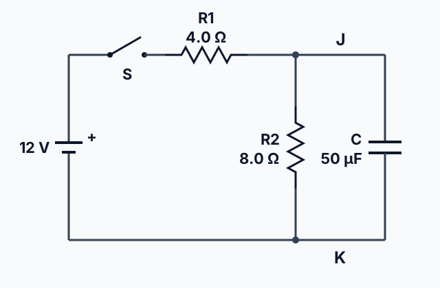
In the circuit at the top of this lesson, an ideal 12 V battery, an open switch S and are on the top wire. Past , and an uncharged 50 F capacitor each join wire J to wire K. The wires are ideal. S is closed. How much charge is on the capacitor a long time later?
Predict first
Before you open the first step, predict: just after S closes, which resistor carries current?
Step 1 · Just after the switch closes
The capacitor is uncharged, so it acts like a wire joining J to K. Then has no potential difference across it and carries no current: all the charge flows through and onto the capacitor. The loop through the battery, and the capacitor gives , so A.
Step 2 · A long time later
The capacitor is fully charged, so its branch carries no current and it acts like an open switch. Redraw the circuit without it: what is left is the battery, and .
Why this step?
Why can the capacitor end up with less than the battery's 12 V?
It is in parallel with , not with the battery. In the final state current still flows through and , so takes part of the 12 V and the capacitor has only what is across .
Your step · Calculate
Finish it. An ideal 12 V battery, a switch and a 4.0 resistor are in series on the top wire of a circuit. Past the resistor, an 8.0 resistor and an uncharged 50 F capacitor each join the top wire to the bottom wire, which returns to the battery. The wires are ideal. The switch is closed. How much charge is on the capacitor a long time later? Give your answer to the nearest microcoulomb.
µC
Part 4 Try it Rank, decide, sort
The next question describes four circuits in words. Rank them before you work anything out, then check your ranking with the time constant, combining the capacitors first.
Try it · Rank it
Four circuits each charge capacitors, uncharged at first, from the same ideal battery through resistors, using ideal wires. Every resistor has resistance R and every capacitor has capacitance C. Circuit 1 has one resistor and one capacitor. Circuit 2 has two resistors in series and one capacitor. Circuit 3 has one resistor and two capacitors in parallel. Circuit 4 has one resistor and two capacitors in series. Rank the circuits by how long their capacitors take to reach 63 percent of their final charge.
Longest time first
Give each one a place, 1 for first. Give two the same place if they are equal.
Your ranking: none yet
Now let a charged capacitor run a bulb. Predict first: what does the bulb do as the capacitor empties?
Try it · Decide and justify
A capacitor is fully charged and then disconnected from its battery. It is then joined across a bulb by ideal wires, and the bulb lights. Treat the bulb's resistance as fixed. Does the bulb get dimmer as time goes on?
Which reason supports your answer?
Try it · Sort it
An uncharged capacitor, a resistor and an ideal battery are on a single path with no branches, and a switch is closed. Tap a card, then choose when it is true.
Just after the switch closes
A long time after
Part 5 Explain it Sketch it, derive it, connect them
On the exam this is handwritten, so answer on paper first. Nothing you type here leaves this page. Then check your answer against the model and each scoring point.
Free response is 50% of the exam score. This one is shaped like Question 2, Translation Between Representations.
Free-response practice · Question 2 style
An uncharged capacitor of capacitance , a resistor of resistance , an open switch and an ideal battery of emf are joined by ideal wires on a single path with no branches. The switch is closed at time .
(a) On paper, sketch two graphs against time after the switch closes: the potential difference across the capacitor, and the current in the resistor. Mark the starting and final value of each on its vertical axis. No time scale is needed. Do this by hand before you open the model.
(b) Derive expressions for the current in the resistor just after the switch closes and for the charge on the capacitor a long time later, in terms of , and .
(c) Explain how the starting and final values on your graphs agree with your expressions in (b).
Model answer
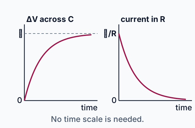
(a) Compare with the graphs below. The potential difference starts at 0, rises steeply and then more slowly, and levels off at . The current starts at , falls steeply and then more slowly, and levels off toward 0.
(b) Just after closing, the capacitor is uncharged, so and the loop rule gives : . A long time later the current is zero, so the resistor has no potential difference, the loop rule gives , and .
(c) The current graph starts at , which is , while the potential difference graph starts at 0 because an uncharged capacitor acts like a wire. At the end the current reaches 0 and the potential difference reaches , which is with .
 Tap to open the picture full size
Score your own answer. This is a self-check, not a grade. Tick each point your answer makes.
Part 6 Check yourself Three bulbs and a capacitor
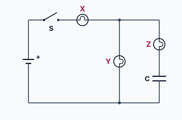
Both case questions use the circuit.
 Tap to open the picture full size
Case question 1 · Rank it
Three identical bulbs, each with a fixed resistance, an ideal battery, ideal wires and an open switch S are connected. Bulb X is on the main wire next to S. Past X the circuit splits into two branches that meet again: one holds bulb Y, and the other holds bulb Z in series with an uncharged capacitor. A bulb's brightness is set only by its power. Rank the bulbs by brightness just after S closes.
Brightest first
Give each one a place, 1 for first. Give two the same place if they are equal.
Your ranking: none yet
Case question 2 · Multiple choice
In the same circuit of three identical bulbs, the capacitor charges from the moment S closes until a long time later. How does each bulb's brightness change over that time?
The rest stand on their own and do not use the case.
Check yourself · Calculate
A 100 F capacitor charged to 9.0 V is disconnected from its battery and then joined across a 30 resistor by ideal wires. What is the current in the resistor just after it is joined? Give your answer to the nearest 0.01 A.
Check yourself · Select all
Three capacitors have capacitances of 2.0 F, 3.0 F and 6.0 F. Which two statements are true? Pick two.
Select 2 answers, then check.
Check yourself · Put it in order
A student wants to watch a capacitor discharge and find the time constant from her data. Her circuit has a battery, a resistor, a capacitor and a two-way switch. In position 1 the battery charges the capacitor through the resistor; in position 2 the battery is out of the circuit and the capacitor discharges through the same resistor. The resistor stays in both loops so that the uncharged capacitor, which first acts like a wire, never joins the battery's terminals directly, which would short the battery. An ideal voltmeter reads the capacitor's potential difference, which is proportional to its charge, and she has a timer. Tap her steps in order.
Part 7 Keep it Bring back earlier ideas
An RC circuit's first and final states are solved with the junction rule and by telling series connections from parallel ones. Pulling them back up is what makes them last.
From 11.7 Kirchhoff’s Junction Rule · Calculate
Five wires meet at junction J in a circuit with steady currents. Wire 1 carries 3.0 A into J, wire 2 carries 1.5 A into J, wire 3 carries 2.0 A out of J and wire 4 carries 0.5 A out of J. What is the current in wire 5? Count a current out of J as positive and one into J as negative. Give your answer to the nearest 0.1 A.
From 11.5 Compound Direct Current (DC) Circuits · Select all
A battery's positive terminal is joined by a wire to resistor . Past the wire is J, and resistors , 6 , and , 12 , each join J to a wire K that returns to the battery's negative terminal. All the wires are ideal. Which two statements are true? Pick two.
Select 2 answers, then check.
In three lines
- Parallel capacitances add; in series the inverses add, every capacitor holds the same charge, and is less than the smallest.
- Just after a switch closes an uncharged capacitor acts like a wire; after a long time a charged one acts like an open switch, and its branch carries no current.
- The time constant measures how quickly charging and discharging run: about 63 percent charged, or 37 percent left, after one time constant.
Exam strategy for this topic
- Section I, Multiple Choice: 42 questions in 85 minutes.
- Section II, Free Response: 4 questions in 95 minutes.
- This lesson's Explain it is shaped like free-response question 2, Translation Between Representations.
- A four-function, scientific, or graphing calculator is allowed on both sections of the exam.
For any RC circuit, draw it twice: once with each uncharged capacitor replaced by a wire, for the instant a switch closes, and once with each capacitor removed, for a long time later. Solve each with the rules you already have, and describe what happens in between in words or sketches.
Questions students ask
How do you combine capacitors in series and in parallel?
In parallel, add them: . In series, add the inverses: , then take the inverse. A 3.0 F and a 6.0 F capacitor give 9.0 F in parallel and 2.0 F in series.
Why do capacitors in series have the same charge?
The plates between two series capacitors, joined by a wire, are cut off from the rest of the circuit, and their total charge stays zero. Whatever charge gathers on one of those plates, the opposite charge gathers on the other.
Does current flow through a capacitor?
No charge crosses the gap between the plates, but while a capacitor charges or discharges, charge flows onto one plate and off the other, so the branch carries a current. Once the capacitor is fully charged, the current in its branch stops.
What does a capacitor act like just after a switch closes, and after a long time?
Uncharged, just after a switch closes, it acts like a wire, with no potential difference across it. Fully charged, after a long time, it acts like an open switch, with no current in its branch.
What is the time constant of an RC circuit?
, a measure of how quickly the capacitor charges or discharges. In one time constant a charging capacitor reaches about 63 percent of its final charge, and a discharging one falls to about 37 percent of its starting charge.
Beyond the AP Exam
College Board sets this limit on what the AP Exam asks about this topic. Anything past it is not on the exam.
Descriptions of charging/discharging RC circuits in AP Physics 2 are limited to qualitative descriptions and representations. While students should be able to mathematically describe initial and final states of RC circuits, students are not expected to mathematically model these behaviors with respect to time.
Course alignment, for teachers
AP Physics 2: Algebra-Based topic 11.8, Unit 11: Electric Circuits.
- Skill 1.B: Create quantitative graphs with appropriate scales and units, including plotting data.
- Skill 1.C: Create qualitative sketches of graphs that represent features of a model or the behavior of a physical system.
- Skill 2.A: Derive a symbolic expression from known quantities by selecting and following a logical mathematical pathway.
- Skill 2.D: Predict new values or factors of change of physical quantities using functional dependence between variables.
- Skill 3.A: Create experimental procedures that are appropriate for a given scientific question.
- Skill 3.C: Justify or support a claim using evidence from experimental data, physical representations, or physical principles or laws.
This lesson maps all 17 essential knowledge statements of the topic to the part that teaches each one: 17 are checked by a scored question. The map is in the lesson file.