Unit 5 · Topic 5.3 · about 30 minutes · 7 parts · 12 scored checks, 2 of them multiple choice, plus 2 from earlier lessons
AP Physics C: Mechanics 5.3: Torque
Unit 5: 10 to 15% of the multiple-choice section
What you'll be able to do
- Identify the torques exerted on a rigid system: which forces turn it about an axis, using the perpendicular component of each force or its lever arm.
- Describe the torques exerted on a rigid system with a force diagram and with , giving each torque's size and its sense, clockwise or counterclockwise.
Key vocabulary
| Term | What it means | The exam trap |
|---|---|---|
| Rigid system | A system whose shape does not change, so every part of it turns together about the same axis. | Rigid is a model choice, like treating an object as a point; it stops fitting when the system bends or stretches enough to matter. |
| Axis of rotation | The line a rigid system turns about, such as a hinge line or an axle. | A torque is always about a chosen axis, and the same force can exert a different torque about a different axis, so name the axis first. |
| Position vector | The vector from the axis of rotation to the point where a force is exerted. | It starts on the axis, not at the origin of your coordinates or the system's center, unless the axis happens to pass through there. |
| Torque | The turning effect of a force about an axis, , which comes only from the force component perpendicular to . | Torque and work share the unit N·m, but they are different quantities, and a torque is never written in joules. |
| Line of action | The line through a force arrow, extended in both directions. | The line runs past both ends of the arrow, so the nearest point to the axis is often on the extension, not on the arrow itself. |
| Lever arm | The perpendicular distance from the axis of rotation to the line of action of a force, . | A lever arm is measured to a line, not to a point on the object; check which one your distance reaches before you multiply. |
| Force diagram | A diagram like a free-body diagram that shows the relative size and direction of each force on a rigid system and also where each force is exerted relative to the axis. | Arrow lengths still show relative sizes, as on a free-body diagram, so a larger force gets a longer arrow. |
| Cross product | A product of two vectors, , whose result is itself a vector, found from the two sizes and the angle between the vectors. | A cross product is a vector, not a number, so it needs a direction as well as a size; it is a different product from the dot product. |
| Right-hand rule | A way to find the direction of a cross product: fingers along the first vector, curled toward the second, thumb along the result. | Turning the thumb's direction into clockwise or counterclockwise depends on which side you look from, so state the viewpoint every time. |
 Tap to open the picture full size
Part 1 Think first A tug of war on a door
Commit to a guess first. Being wrong now makes the right idea stick better.
Predict first
You push on a door's handle, 0.80 m from its hinges, to open it. On the other side, a friend pushes to close it with exactly the same size of force, also straight against the face of the door, but she pushes halfway between the handle and the hinges. What does the door do?
In short. Torque is the turning effect of a force about an axis, , with size : only the part of the force perpendicular to the position vector from the axis turns a rigid system.
- Measure from the axis to the point where the force is exerted; the torque's size is , or equally , where the lever arm is the perpendicular distance from the axis to the force's line of action.
- A force diagram is drawn like a free-body diagram but puts each arrow where its force is exerted, so the lever arms can be read off it.
- The cross product points along the axis, perpendicular to both and ; describe it as clockwise or counterclockwise as seen from a stated side.
Part 2 Learn it Four ideas, with a check after each
3a. Only the perpendicular part turns it
A rigid system keeps its shape, so it can turn as one piece about an axis of rotation: a hinge line, an axle, a bolt's center. To ask what a force does to its rotation, draw the position vector from the axis to the point where the force is exerted.
Now split the force into two components. The part along pulls the system straight away from the axis or pushes it straight in, and an axle or hinge resists that without any turning. Only the part perpendicular to turns the system. If is the angle between and , drawn tail to tail, that part is , and the size of the torque is
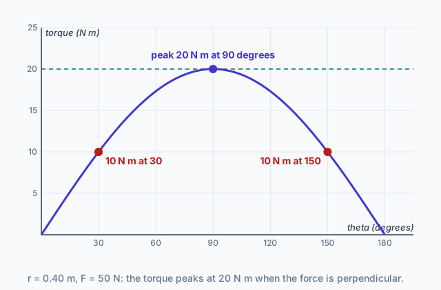
Torque is measured in newton meters, N·m. The graph at the top of the page plots it for a 50 N force exerted 0.40 m from an axis: 20 N·m when the force is perpendicular to , half that at 30°, and nothing at 0° or 180°, where the whole force lies along .
Quick check · Calculate
A mechanic grips a wrench 30 cm from the center of a bolt and pulls with a 120 N force. Her pull makes a 30° angle with the wrench handle, which runs straight from the bolt's center to her hand. What is the size of the torque her pull exerts on the bolt about its center?
3b. The lever arm
There is a second way to get the same number. Extend the force arrow into a full line in both directions: its line of action. The lever arm is the perpendicular distance from the axis to that line. Then
The two routes agree because : a right triangle with as its hypotenuse has as the side opposite , so and are the same product. A force exerted 1.2 m from an axis at 30° to has a lever arm of 0.60 m.
The lever arm is the easier route when the picture hands you a distance to a line, such as a cable running at a slant, and the angle with would take work to find.
It also shows the zero cases at a glance. A force whose line of action passes through the axis has no lever arm, so it exerts no torque about that axis, however large it is. That is why the force an axle or a hinge exerts on a system never turns it about that axle or hinge.
Quick check · Calculate
A 4.0 m post stands upright on a hinge at its base, so it can tip toward a stake in the ground 3.0 m from the base. A taut rope runs in a straight line, at a slant, from the top of the post to the stake, and the tension in the rope is 250 N. What is the size of the torque the rope exerts on the post about the hinge?
3c. Force diagrams show where
A free-body diagram shrinks the system to a dot, which is right for asking how its center of mass accelerates. It cannot show torques, because a torque depends on where each force is exerted.
A force diagram is drawn like a free-body diagram, with each force as a straight arrow whose length shows its relative size and whose direction is the force's direction. The difference is that the system is drawn with its real extent, the axis is marked, and each arrow starts at the point where that force is exerted. From it you can read , the angle and the lever arm for every force.
Picture a rod lying on a frictionless table, turning about a vertical axle through one end, seen from above. Its force diagram shows the rod as a line, a dot at the axle, the arrow for the axle's force starting at that dot, and each pull on the rod starting where its string is tied.
Two forces that cancel as forces can still both turn a system the same way. A force diagram makes that visible; a single dot hides it.
Quick check · Decide and justify
A driver holds a steering wheel of radius 0.18 m at the 9 o'clock and 3 o'clock positions. Her left hand pulls down on the rim with 30 N, and her right hand pushes up on the rim with 30 N. Seen from the driver's seat, take counterclockwise as positive. A classmate draws a free-body diagram with both forces on one dot, sees that they add to zero, and says the hands exert no net torque on the wheel about its axle. Is the classmate right?
Which reason supports your answer?
3d. Torque as a cross product
Torque is a vector, the cross product of the position vector and the force:
For any two vectors, has size , which for torque is the of the first idea. Its direction is perpendicular to both vectors, so it is normal to the plane they lie in. For a force in the plane of turning, that means the torque points along the axis.
The right-hand rule finds which way along the axis: point your fingers along , curl them toward , and your thumb points along . In this course you report the result as a sense of turning. A thumb pointing toward you means the system tends to turn counterclockwise as you see it; a thumb pointing away means clockwise. Order matters: points the other way.
With to the right and up on the page, the components give it directly:
A positive is counterclockwise as seen from the front. A wrench pointing left from a bolt, m, pushed up with N, gives N·m: clockwise.
Quick check · Fill the statement
A 0.30 m wrench points straight to the right from the center of a bolt, and you push straight up on its end with a 50 N force. You look at the wrench from the front.
Here has size . It points along the bolt's axis, to the plane that holds and , and seen from the front your push tends to turn the bolt .
Part 3 Watch it done Three pulls on a rod
Watch each step, then do the last one yourself.
A 1.2 m rod lies on a frictionless horizontal table and can turn about a vertical axle through its west end; at this instant it points due east from the axle. Seen from above, take counterclockwise as positive. Three horizontal forces are exerted on the rod: 20 N due north at its east end, 30 N directed 30° south of east at its midpoint, and 40 N due east at its east end. What is the net torque on the rod about the axle?
Step 1 · Draw the force diagram
Draw the rod from the axle east to 1.2 m, and start each arrow where its force is exerted: the 20 N north and the 40 N east at the end, the 30 N at 0.60 m. The axle also pushes on the rod, but that arrow starts on the axis, so and its torque is zero. The rod's weight and the table's upward push are vertical, along the axle's direction, and they balance; they are left out of the top view.
Step 2 · Torque of each force
The 20 N pull is perpendicular to : N·m, and east then north is a counterclockwise turn, so N·m. The 30 N pull makes 30° with and leans south: N·m, clockwise. In components, N·m, the same.
Why this step?
Why does the 40 N pull, the largest force, add nothing?
It points due east, straight along , so the angle between them is 0° and . Its line of action runs along the rod through the axle, so its lever arm is zero. It pulls the rod against the axle without turning it.
Your step · Calculate
Finish it. What is the net torque on the rod about the axle? Counterclockwise as seen from above is positive.
N·m
Part 4 Try it New situations
Try it · Sort it
Seen from above, a door's hinge line is at its west edge and the door runs due east from it to the handle. Counterclockwise as seen from above is positive. Every force listed is horizontal. Tap a card, then say which way it tends to turn the door about the hinge line.
Counterclockwise
Clockwise
No torque
Try it · Multiple choice
A flat plate turns about an axle perpendicular to the page through the origin, with to the right and up on the page. A force N is exerted on the plate at m from the axle. Seen from the front, counterclockwise is positive. What torque does the force exert about the axle?
On paper. Draw the force diagram for the rod in Watch it done as seen from above: the rod as a 1.2 m line pointing east, a dot at the axle, and each of the three pulls and the axle's force as an arrow that starts where it is exerted, with lengths in proportion to the forces. Then extend the 30 N arrow into its line of action and draw the lever arm as a segment from the axle that meets that line at a right angle. There is nothing to submit; check that your lever arm comes out near m to the scale of your drawing.
Part 5 Explain it Draw it, derive it, graph it, connect them
Nothing you type leaves this page. Check your answer against the model and each scoring point.
Free response is 50% of the exam score. This one is shaped like Question 2, Translation Between Representations.
Free-response practice · Question 2 style
A thin rod of length lies on a frictionless horizontal table and turns about a vertical axle through its end at the origin. Seen from above, points east and points north, and counterclockwise as seen from above is positive. At this instant the rod lies along the positive axis. A student pulls on a string tied to the rod a distance from the axle, with a horizontal force of constant size directed at an angle north of east, where .
(a) On paper, draw a force diagram of the rod as seen from above. Show each horizontal force exerted on the rod as an arrow starting at the point where it is exerted, and mark the axle.
(b) Write and for the string's pull in unit-vector form. Derive an expression for the torque the string exerts on the rod about the axle, in terms of , and , and state its sense.
(c) On paper, sketch the size of the string's torque as a function of , from to , with and held fixed. Label the value at .
(d) Use your force diagram from part (a) to find the lever arm of the string's pull. Justify why the torque you get from the lever arm agrees with your answer to part (b), and explain why the axle's force exerts no torque about the axle.
Model answer
(a) A horizontal line from a dot at the axle east to length . One arrow starts on the rod at distance and points at north of east, labeled . A second arrow, for the axle's force on the rod, starts at the axle dot. Compare your diagram with this: the point is where each arrow starts.
(b) and . Then . It is positive, so the torque is counterclockwise as seen from above.
(c) A straight line through the origin, rising with slope , ending at at . Compare your sketch with that shape and that label.
(d) The line of action passes through the point at angle to the rod, so the perpendicular distance from the axle to it is . Then , the same as part (b). They agree because both keep only the perpendicular geometry: part (b) multiplies by the perpendicular part of the force, , and the lever arm multiplies by the perpendicular part of the distance, . The axle's force is exerted at the axle, where , so its torque about the axle is zero.
Score your own answer. This is a self-check, not a grade. Tick each point your answer makes.
Part 6 Check yourself Pushing a lab door
The case questions use the table of trials. Answer them from it.
A class tests a 0.90 m wide lab door that turns about a vertical hinge line along one edge. In each trial a student pushes horizontally on the door, measuring the push with a force sensor, its distance from the hinge line with a meter stick, and with a protractor the angle between the push and the line from the hinge line to the point where she pushes. Every push tends to open the door, which is counterclockwise as seen from above, the positive sense.
| Trial | Distance from hinge line (m) | Push (N) | |
|---|---|---|---|
| A | 0.80 | 25 | 90° |
| B | 0.60 | 40 | 30° |
| C | 0.50 | 40 | 90° |
| D | 0.80 | 35 | 150° |
Case question 1 · Multiple choice
Which two trials exert torques of the same size on the door about the hinge line?
Case question 2 · Calculate
What is the lever arm of the push in trial B about the hinge line?
Case question 3 · Rank it
Rank the four trials by the size of the torque each push exerts on the door about the hinge line.
Greatest first
Give each one a place, 1 for first. Give two the same place if they are equal.
Your ranking: none yet
The rest stand on their own and do not use the case.
Check yourself · Spot the error
A 60 N force is exerted on the end of a 0.50 m bar that turns about an axis through its other end. The force makes a 30° angle with the bar. A student finds the size of the torque about the axis. Tap the first line with a mistake.
Check yourself · Match
Each term describes the torque of a force exerted in the plane of the page on a system that turns about an axis perpendicular to the page. Tap a term, then what it is.
Part 7 Keep it Bring back earlier ideas
This lesson stands on signed quantities from Topic 1.2, a sign that stands for a direction, and on rigid rotation from Topic 5.2, where every point of a turning system shares one angular motion about the axis while its distance from the axis sets its linear motion.
From 1.2 Displacement, Velocity, and Acceleration · Calculate
A tennis ball flies toward a wall at 30 m/s and bounces straight back at 20 m/s. It touches the wall for 0.010 s. Take the direction toward the wall as positive. What is the ball's average acceleration while it touches the wall?
From 5.2 Connecting Linear and Rotational Motion · Sort it
A rigid wheel speeds up as it turns about a fixed axle. Tap a card, then say whether the quantity is the same for every point on the wheel or depends on the point's distance from the axle.
Same for every point
Depends on distance from the axle
In three lines
- Torque about an axis comes only from the part of a force perpendicular to : , in N·m.
- Equally, , with the lever arm measured from the axis to the force's line of action; a force through the axis exerts no torque.
- A force diagram puts each arrow where its force is exerted, and gives the sense, clockwise or counterclockwise as seen from a stated side.
Exam strategy for this topic
- Section I, Multiple Choice: 42 questions in 85 minutes.
- Section II, Free Response: 4 questions in 95 minutes.
- This lesson's Explain it is shaped like free-response question 2, Translation Between Representations.
- A four-function, scientific, or graphing calculator is allowed on both sections of the exam.
On a free-response question about torque, start with a force diagram that puts every arrow where its force is exerted and marks the axis, then write or before any numbers. State the positive sense, clockwise or counterclockwise and from which side, and give every torque its sign before you add them.
Questions students ask
Do I need the right-hand rule for this course?
You use it to decide whether a torque turns a system clockwise or counterclockwise as seen from a stated side. This course limits rotational directions to clockwise and counterclockwise about a given axis, so you use the rule to find that sense rather than to name a direction in space.
Should I use or the lever arm?
Either gives the same torque. Use when you know the angle between and the force, and the lever arm when the picture gives you the perpendicular distance to the force's line, such as a cable at a slant.
How is a force diagram different from a free-body diagram?
Both show each force as an arrow with its relative size and direction. A free-body diagram puts every arrow on one dot; a force diagram draws the system with its axis and starts each arrow where the force is exerted, which is what you need to find torques.
Can a force exert a torque if the net force on the system is zero?
Yes. Two equal and opposite forces whose lines of action pass on opposite sides of an axis add to zero as forces but both turn the system the same way. Net force and net torque are separate questions.
Is a newton meter of torque the same as a joule?
They have the same base units, but torque is a turning effect and work is an energy transfer. Write torque in N·m and keep joules for energy.
Course alignment, for teachers
AP Physics C: Mechanics topic 5.3, Unit 5: Torque and Rotational Dynamics.
- Skill 1.A: Create diagrams, tables, charts, or schematics to represent physical situations.
- Skill 2.B: Calculate or estimate an unknown quantity with units from known quantities, by selecting and following a logical computational pathway.
- Skill 2.C: Compare physical quantities between two or more scenarios or at different times and/or locations within a single scenario.
- Skill 3.C: Justify or support a claim using evidence from experimental data, physical representations, or physical principles or laws.
This lesson maps all 9 essential knowledge statements of the topic to the part that teaches each one: 9 are checked by a scored question. The map is in the lesson file.